
The service life of a glass glass furnace is closely related to glass furnace design, refractory material selection, daily maintenance, glass formulation, and masonry quality. Therefore, glass furnace masonry must adhere to scientific, rigorous, and meticulous principles. Establishing industry-specific standards and specifications for glass glass furnace masonry is crucial for improving glass furnace longevity.
Currently, common types of glass glass furnaces in the industry include cross-fired glass furnaces, horseshoe flame glass furnaces, full-oxygen glass furnaces, and all-electric melt glass furnaces. Among these, cross-fired and horseshoe flame glass furnaces occupy larger footprints, feature complex structures, and require numerous auxiliary equipment, making their masonry more challenging and demanding. This study takes a regenerative horseshoe flame glass furnace as an example and discusses key points and considerations in glass furnace masonry, covering aspects such as glass furnace foundation calibration and positioning, column installation, checkerwork arch construction, regenerator wall masonry, cylindrical brick placement, and tank bottom insulation layer construction.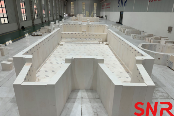
1. Foundation Calibration and Positioning
2. Installation of glass furnace Steel Columns
3. Checkerwork Arch Construction
4. Masonry of Regenerator Walls and Expansion Joint Reservation
5. Checker Brick Placement
6. Masonry of Tank Bottom Insulation Bricks
1. Foundation Calibration and Positioning
Precise glass furnace positioning is the primary factor ensuring construction according to design dimensions. When positioning the glass furnace, adjustments must be made based on the casting conditions of the glass furnace foundation. Typically, the glass furnace foundation is cast from reinforced concrete. Due to limitations in the casting process, the levelness of the regenerator foundation and the height of the reinforced concrete support columns often deviate from the design specifications. Therefore, before masonry begins, the levelness of the regenerator foundation and the height of the reinforced concrete columns must be calibrated.
1.1 Foundation Levelness
The cast surface of the regenerator foundation is generally required to have a height deviation of no more than 10 mm. However, in practice, deviations often exceed this range. Excessive errors make it difficult to meet masonry requirements. To ensure the foundation‘s levelness aligns with the design, leveling materials can be used for adjustment, followed by compaction to ensure stability. Figure 1 shows a typical on-site condition of the regenerator foundation casting, while Figure 2 illustrates the leveled and compacted regenerator foundation.


1.2 Concrete Columns
The load-bearing capacity of the reinforced concrete columns is calculated and designed based on factors such as glass furnace size, glass melt tonnage, refractory materials, and steel weight. The civil engineering team designs the dimensions of the concrete columns according to geological conditions and load requirements. Based on practical experience, it is recommended to leave a certain space at the top of the columns uncast during the initial pouring. The remaining portion should be cast only after the actual height of the columns is verified during the pre-masonry stage, as shown in Figure 3. This approach is necessary because concrete casting often introduces dimensional errors. If the columns are fully cast in one step, it becomes challenging to adjust the flatness and height of the column tops later.

Figure 3 also shows that a 20–30 mm thick iron plate is placed at the top of each reinforced concrete column. This plate is used to adjust the flatness and height of the column tops during the supplementary concrete casting. Typically, within 15 days before masonry begins, the height and levelness of the reserved iron plates are adjusted based on the actual measured column heights, after which the concrete is poured. To enhance the bonding between the iron plates and the concrete, each plate should have one pouring hole (80–100 mm in diameter) and two vent holes (30–50 mm in diameter) to release air beneath the plate and ensure tight integration between the concrete and the plate.
1.3 Glass Furnace Positioning
1.3.1 Calibration of the glass furnace Base "Zero" Level

After leveling the regenerator foundation, the horizontal "zero" level of the glass furnace must be established. Typically, glass furnace designers use the level ground beneath the concrete columns as the "zero" reference. However, discrepancies often arise between the theoretical design dimensions and the actual dimensions during the casting of the regenerator foundation and the factory floor. If the original factory floor level is still used as the reference "zero," the actual masonry dimensions may deviate from the design drawings. Therefore, the "zero" level must be redefined based on the actual glass furnace foundation conditions.
The new "zero" level can be determined using the height marked on the regenerator foundation drawings, and the gob (glass droplet) level line (i.e., gob height) can then be calibrated accordingly. Figures 4 and 5 illustrate the standard glass furnace foundation design and an on-site example of recalibrating the "zero" level, respectively.

1.3.2 Marking the glass furnace‘s Longitudinal Centerline, Transverse Centerline, and Related Outlines
When marking the longitudinal centerline of the glass furnace, ensure that the regenerator‘s longitudinal centerline aligns with the melting tank‘s longitudinal centerline. The regenerator‘s longitudinal centerline should be marked first, followed by the melting tank‘s centerline and corresponding outlines. Clear markings are essential to guide subsequent masonry work.
Typically, glass furnace masonry begins with the regenerator before proceeding to the melting tank. Alternatively, both sections can be constructed simultaneously. In either case, proper workforce allocation and construction progress control are crucial to ensure convergence at the burner ports. The charging port centerline serves as the connection between the regenerator and melting tank masonry, providing a precise reference for positioning all masonry lines in the melting tank.
Figure 6 shows on-site photos of glass furnace marking, including:
The calibrated longitudinal centerline and related outlines after leveling the regenerator foundation.
The outline of the regenerator‘s triple flue.
The melting tank‘s longitudinal centerline and charging port centerline.

Standard glass furnace masonry requires recalibrating construction lines or centerlines after completing each layer or section to ensure adherence to design dimensions. Relying solely on the workers‘ experience may lead to quality defects.
2. Installation of glass furnace Steel Columns
The steel structure of the glass furnace is a critical component that supports the refractory materials and the glass melt. Its installation must strictly follow specifications to ensure overall glass furnace quality. Once positioned and welded, the steel structure typically remains stable for years without major adjustments. Neglecting installation standards can weaken the structure‘s support, causing refractory materials to loosen, crack, or even collapse locally.

Columns are the most important elements of the glass furnace‘s steel structure, primarily including those for the melting tank and regenerator. Their positioning and adjustment require simultaneous use of laser levels and spirit levels. To correct vertical alignment, adjustments must be made in both lateral (left-right) and longitudinal (front-back) directions—single-sided correction is insufficient. Tools like turnbuckles (Figure 7) can assist in fine-tuning column verticality.
The base of regenerator columns must be embedded in foundation pits to withstand outward thrust forces. Key requirements include:
Minimum embedment depth: ≥300 mm.
Reinforcement bars around the pit perimeter, cast integrally with the regenerator foundation.
3. Checkerwork Arch Construction
The checkerwork arch is a vital structure in the regenerator, supporting the cylindrical bricks. Poor construction can lead to brick collapse and accelerated clogging.
Construction Requirements:
Surface Flatness: The arch‘s upper surface must be level. Use spirit levels or straightedges during construction to ensure stability and even load distribution for the cylindrical bricks.
Center Leveling: When reaching the arch center, use castable refractory for leveling instead of cutting bricks, as the latter lacks comparable flatness and durability.
Figure 8 demonstrates:
A checkerwork arch leveled with castable refractory.
On-site leveling verification using a spirit level.
Horizontal alignment checked with a straightedge.
By adhering to these practices, the checkerwork arch’s integrity and longevity are significantly enhanced.

4. Masonry of Regenerator Walls and Expansion Joint Reservation
4.1 Wall Masonry
The masonry work of regenerator walls may appear simple but often encounters problems. This primarily occurs when construction guidelines or marking lines are not properly established during the building process, leading to wall tilting - particularly noticeable at the top section. After kiln heating, the tilting of the regenerator top wall tends to worsen, frequently necessitating additional steel structure reinforcement to prevent collapse.
Standardized wall masonry should employ contour marking lines to ensure proper wall alignment without tilting, as illustrated in Figure 9. Regular height markings should also be implemented to maintain the wall height within design specifications, shown in Figure 10. The mortar thickness on refractory brick surfaces should optimally be controlled at approximately 2 millimeters. Excessive mortar thickness may lead to post-construction wall cracking and flame penetration.

Height markings should be made every 10 layers of refractory bricks, clearly indicating the masonry line for each layer while monitoring any deviations between actual construction height and marked lines to adjust mortar thickness accordingly. Additionally, as demonstrated in Figure 10, not only should height measurements be taken vertically, but guideline strings should also be used at wall corners to ensure perfectly plumb alignment from top to bottom.
4.2 Expansion Joint Reservation
The lower section of regenerator walls typically utilizes clay-based brick materials where temperatures remain relatively low with minimal thermal expansion, thus requiring no expansion joints. However, the middle and upper sections of the regenerator may reach temperatures between 800-900 degrees Celsius or higher, necessitating high-temperature resistant and erosion-proof materials that typically exhibit significant thermal expansion. Therefore, expansion joints must be reserved during masonry to ensure wall stability.
The size of expansion joints for each layer of hard bricks within the wall structure should follow design specifications. When joint dimensions are not specified in drawings, they should be determined based on the expansion coefficient of different brick materials, operating temperatures, and wall length. The outermost layer of lightweight insulating bricks generally requires no expansion joints. Typically, foam boards with customizable thicknesses of 5, 10, or 20 millimeters are used as expansion joint spacers to accommodate various joint size requirements. Figure 11 illustrates the expansion joint arrangement in regenerator walls.


To prevent flame penetration through walls, expansion joints must be staggered in their placement, as shown in Figure 12. The diagram clearly demonstrates how Expansion Joint 1 and Expansion Joint 2 are offset from each other. If these joints were aligned vertically, high-temperature gases within the regenerator could potentially penetrate through incompletely sealed Expansion Joint 2 after kiln heating, eventually eroding the outermost lightweight insulating bricks and causing wall leakage and flame penetration issues.
5. Checker Brick Placement
While the placement of checker bricks appears relatively straightforward, it demands careful attention to avoid potential hazards. The placement process emphasizes two key principles: "levelness" and "alignment".
The "levelness" refers to horizontal positioning. Due to manufacturing variations in checker brick dimensions and potential unevenness at all four corners, improper placement can result in uneven load distribution, potentially leading to brick fracturing or even complete collapse of the checker structure. Therefore, each brick‘s dimensions and flatness must be thoroughly inspected. Any unevenness should be corrected using castable refractory materials and verified with a straightedge. Figure 13 shows on-site photos of checker brick placement, demonstrating both the use of castable materials for leveling and straightedge verification of flatness.

The "alignment" refers to maintaining consistent vertical and horizontal positioning of all checker bricks. Figure 14(a) illustrates improper placement with misaligned bricks, which creates uneven gaps that obstruct exhaust flow, increase airflow resistance, and allow dust particles to accumulate on rough brick surfaces and in misaligned joints. Such accumulation eventually leads to accelerated clogging of checker bricks, a common cause of regenerator blockage in most glass glass furnaces.
For optimal results, custom alignment templates should be used for checker brick placement to ensure perfect vertical and horizontal alignment, as shown in Figures 14(b) and 14(c). These demonstrate properly arranged checker bricks with consistent positioning in all directions and perfect vertical alignment. The template width should match the checker brick dimensions, with clear position markers indicating proper brick placement. When using these custom templates, bricks should be placed row by row, with the template removed after completing each row before proceeding to the next.

6. Masonry of Tank Bottom Insulation Bricks
6.1 Staggered Joints for Insulation Bricks
The staggered joint masonry technique ensures enhanced structural stability for the tank bottom insulation bricks. Careless construction practices that disregard brick levelness and proper joint staggering will result in substandard masonry quality. Figure 15 illustrates comparative examples of correctly and incorrectly executed staggered joint masonry.

6.2 Levelness of Insulation Layer
The tank bottom insulation bricks must not only be laid with staggered joints but also meet stringent levelness requirements. This guarantees proper flatness for subsequent layers including castable blocks, melting tank paving bricks, and melting tank wall bricks, ensuring tighter fitting between wall bricks with more uniform joints. After completing the insulation brick masonry, verify levelness using a straightedge and grind any uneven areas with an angle grinder. These specifications form the foundation for constructing high-quality glass furnaces, requiring strict compliance and standardized operation by construction teams. Figure 16 demonstrates the verification and grinding process during tank bottom insulation brick installation.

6.3 Offset Placement of Lightweight Insulation Bricks from Castable Block Joints
The typical design of domestic flame glass furnace tank bottom insulation layers follows the configuration shown in Figure 17.  This design features clay bricks installed beneath the joints of castable blocks, with lightweight insulation bricks deliberately offset from these joints. This configuration prevents potential erosion of lightweight insulation bricks by molten glass that might penetrate through the joints, thereby avoiding material leakage. During field construction, precise calculation, measurement and marking of all castable block joint positions are mandatory to ensure proper offset when laying lightweight insulation bricks.
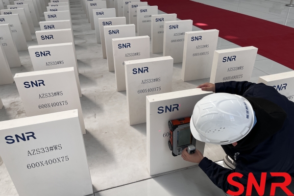

Henan SNR Refractory Co., Ltd. has been specializing in the production of fused cast AZS blocks for about 25 years. We use high-quality raw materials and advanced fusion technology to provide customers with high-quality products. From raw material procurement to finished product delivery, every step is strictly quality inspected to ensure that every indicator meets the standards, so you can use it with confidence.
 If you have any needs, you can contact me at any time.
Web:www.snr-azs.com
Email:wendy@snrefractory.com
 info@snr-azs.com
 +86-18203976036