
Glass furnace in domestic glass industry is the main source of carbon emission. So far, only a small proportion of glass furnaces have adopted oxy fuel combustion technology in the flat glass industry. By analyzing the scale design and application of oxy-fuel furnace for making ultra-clear glass, the melting capacity of the oxy-fuel furnace is analyzed and calculated. The type and design height of the burner in the melting area are reasonably allocated. The problems related to the structure design and application of the oxy-fuel furnace are solved. Energy saving and consumption reduction, as well as low carbon emission are realized. Practice has proved that the adoption of oxy-fuel combustion technology in the ultra-clear glass industry for energy-saving and consumption reduction and reduction of carbon emissions will be the development trend of the current era and the future.
Introduction
The glass manufacturing industry is one of the high-energy-consuming industries with significant carbon emissions. Glass melting furnaces are the primary source of carbon emissions in the flat glass industry. By the end of 2020, only 5% of the flat glass industry met the energy efficiency benchmark standards, with a target of achieving over 30% by 2025. The energy efficiency benchmarks and benchmark levels for the flat glass industry are outlined in Table 1.
By 2025, production capacity below the energy efficiency benchmark level should be virtually eliminated. Given the characteristics of high energy consumption and high carbon emissions in the flat glass industry, adopting oxygen-fired combustion is an effective approach for energy conservation, emissions reduction, and low-carbon emissions in the glass industry, and it represents the future trend.
Table 1 Energy consumption per unit product of flat glass (kg standard coal/weight box)
|
Product Name |
Benchmark Level |
Target Level |
|
|
Flat glass melting capacity / (t/d) |
≥500, ≤800 |
13.5 |
9.5 |
|
>800 |
12 |
8 |
|
Through years of effort, oxy-fuel combustion furnaces for ultra-clear solar photovoltaic glass have shown a trend toward large-scale production. From the early 240 t/d oxy-fuel combustion furnaces for ultra-clear photovoltaic glass (one glass furnace with two production lines), the industry has now developed main glass furnace types such as 650 t/d (one glass furnace with five lines), 750 t/d, 800 t/d, and 850 t/d (one glass furnace with four lines). The energy consumption per unit of these glass furnaces is 25%-30% lower than that of cross-fired furnaces with the same production capacity. Similarly, oxyfuel combustion is being used in ultra-clear float glass furnaces. In addition to the production line imported from abroad over a decade ago, domestically designed oxyfuel ultra-clear float glass furnaces, primarily 600 t/d and up to 800 t/d, have also been put into operation after years of domestic practice. These glass furnaces have achieved excellent results, and a wealth of experience has been accumulated in the production of ultra-clear glass using oxyfuel combustion technology.
1. Scale Design and Application of Oxy-fuel Ultra-clear Glass Furnaces
Based on the characteristics of oxy-fuel combustion glass furnaces and the specific requirements of ultra-clear glass furnaces, existing cases are analyzed and compared to further improve and develop the oxy-fuel combustion technology and glass furnace structure design in the production of ultra-clear photovoltaic glass and ultra-clear float glass.
1.1 Calculation and Determination of Melting Capacity of Oxy-fuel Ultra-clear Glass Furnaces
The reasonable melting tank area is the main factor determining the melting capacity of glass furnaces and the size of the melting tank for glass furnaces of various scales. The length-to-width ratio of the melting tank and melting zone should have a reasonable range and cannot be arbitrarily lengthened or shortened. For oxy-fuel glass furnaces, the length of the melting tank and melting zone should also have a proportional relationship with the width. When China first introduced the technology of cross-fired ordinary float glass furnaces from the American TECO company, an empirical formula was provided for calculating the melting tank width of glass furnaces with various production capacities:
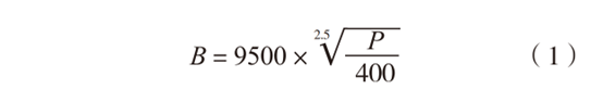
In this formula:
P is the melting capacity, in t/d;
B is the width of the melting tank, in mm.
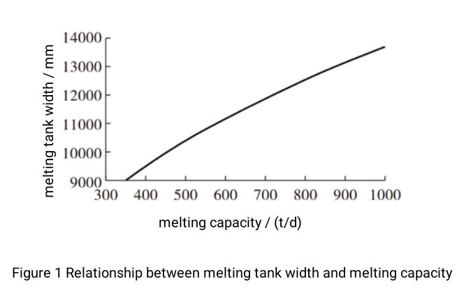
The relationship between melting tank width and melting capacity of cross-fired glass furnaces according to formula (1) is shown in Figure 1.
Using the method of formula (1), comparisons and calculations were made for the length-to-width ratio and furnace width of the early 240 t/d oxy-fuel ultra-clear photovoltaic glass furnace and 600 t/d oxy-fuel ultra-clear float glass furnace introduced in China. In formula (1), the production capacity required for cross-fired furnaces was adjusted from 9500 mm to 8470 mm for oxy-fuel furnaces. This can be applied to determine the melting capacity required for the melting zone width in the design of oxy-fuel ultra-clear glass furnaces.
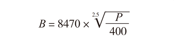
In this formula:
P is the melting capacity, in t/d;
B is the width of the melting tank, in mm.
Based on the above calculations, it is determined that the length-to-width ratio range for oxy-fuel furnaces is K1 = 2.94 ~ 3.2 for the melting tank and K2 = 1.6 ~ 2.4 for the melting zone, which is feasible and reasonable. Therefore, when evaluating the currently operating 750 t/d oxy-fuel ultra-clear photovoltaic glass furnace, with a designed melting tank width of 11 m and the requirement to appropriately increase the length of the clarification zone for ultra-clear glass production, the length-to-width ratio of the furnace is K1 = 3.2, resulting in a length of 35.2 m. The melting rate of oxy-fuel combustion can be increased by about 25% compared to traditional cross-fired furnaces of the same scale. The melting zone was designed with K2 = 2.3. According to statistics, the natural gas consumption per unit of this 750 t/d photovoltaic glass oxy-fuel combustion furnace is less than 4898 kJ/kg, achieving energy savings of about 30% compared to large air-fuel furnaces. At the same time, the flue gas volume and NOx content are significantly reduced, with the lowest NOx emission concentration of 111.5 mg/m³, far below the national environmental standard of 700 mg/m³. NOx emissions are reduced by over 80%, and greenhouse gas CO₂ emissions are reduced by more than 20%, resulting in an annual reduction of about 6100 tons of carbon emissions compared to air-fuel furnaces.
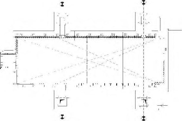
The schematic diagram of the 750 t/d oxy-fuel ultra-clear photovoltaic glass furnace with four production lines is shown in Figure 2.
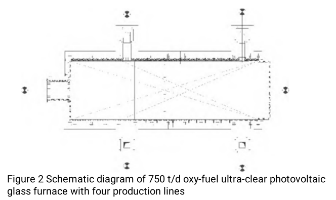
Years of operation of this glass furnace have proven that the evaluation of this oxy-fuel ultra-clear photovoltaic glass furnace is feasible. It fully demonstrates the characteristics of oxy-fuel furnaces, such as high product quality, high yield, high melting rate, and low energy consumption, which are incomparable to conventional cross-fired ultra-clear photovoltaic glass furnaces of the same capacity. Compared with the currently introduced 600 t/d oxy-fuel ultra-clear float glass furnace, with a melting tank width of 10 m and length of 27.3 m, the length-to-width ratio of the melting tank K1 = 2.73 should be relatively close. The main difference is that the clarification zone is not proportionally lengthened. If the length of the clarification zone is excessively increased, the unit heat load required for the flame space in the melting tank will be reduced, affecting the thermal efficiency of the glass furnace. This is also one of the important factors affecting the thermal efficiency of most domestic glass furnaces.
1.2 Requirements for Establishing the Melting Tank in Oxy-fuel Ultra-clear Furnaces
For larger oxy-fuel furnaces, two pairs of horizontal flues are installed on both sides of the breast wall in the melting tank. The range of the melting tank is calculated from the outer edge of the doghouse to 1 m outside the centerline of the rear pair of horizontal flues, which is currently one of the main methods for determining the melting tank in oxy-fuel glass furnaces. According to the control range of the length-to-width ratio ( K2 = 1.6 - 2.4 ) for the melting tank of oxy-fuel ultra-clear photovoltaic glass furnaces mentioned above, the melting area of oxy-fuel glass furnaces of various scales can be calculated.
The heating characteristics of the melting tank are closely related to the glass furnace‘s melting capacity, melting rate per unit area, energy consumption indicators, and operational lifespan (i.e., the four major technical indicators of glass furnaces). The volumetric heat load of the flame space in the melting tank of oxy-fuel furnaces also directly affects the melting capacity and thermal efficiency of the glass furnace. Similarly, a reasonable length-to-width ratio of the melting tank in oxy-fuel furnaces is directly related to the thermal efficiency that the glass furnace should achieve.
The recommended design schematic diagram of the 850 t/d oxy-fuel ultra-clear photovoltaic glass furnace is shown in Figure 3.
The design plan for the 850 t/d oxy-fuel ultra-clear photovoltaic glass furnace: the total length of the melting tank is about 35 m, and the glass furnace width is less than 12 m. The length-to-width ratio is controlled at ( K1 = 3.0 ), and the length-to-width ratio of the melting zone ( K2 ) is about 2.2, calculated from 1 m outside the rear pair of horizontal flues.
1.3 Control of Glass Furnace Melting End Depth in Ultra-clear Glass Furnaces
Due to the low Fe₂O₃ content in ultra-clear glass, its thermal penetration ability is strong, resulting in a relatively small temperature gradient in the depth direction of the glass liquid in the glass furnace. The temperature at the bottom of the melting end is higher than that of ordinary transparent glass. The paving blocks (fused cast AZS blocks) in contact with the glass liquid at the bottom of the melting end generally begin to precipitate a glass phase at 1400 ℃, accompanied by a large number of bubbles. Excessive temperature at the bottom of the melting end not only significantly affects the lifespan of the glass furnace but also seriously pollutes the glass liquid. Appropriately increasing the depth of the melting tank in the glass furnace is beneficial for extending the service life of the paving blocks, but excessive depth will increase the investment in the glass furnace, is not conducive to energy saving and consumption reduction, and has no obvious effect on reducing the temperature at the bottom of the melting end. Therefore, an appropriate melting end depth must be selected.
Some research units have studied the relationship between the depth of ultra-clear glass furnace melting ends and glass melting quality and determined a reasonable melting end depth through computer simulation to ensure glass quality and glass furnace lifespan. Due to the low Fe₂O₃ content in ultra-clear glass, the ability of the glass liquid to radiate heat from the flame is weak, but its thermal penetration ability is relatively strong. Therefore, the temperature gradient of the glass liquid in the depth direction is relatively small. For a glass furnace with a certain melting end depth, the temperature at the bottom of the melting end when producing ultra-clear glass is inevitably higher than when producing ordinary transparent glass. When the depth of the melting tank in an ultra-clear glass furnace is designed to be 1.5 m, the highest temperature at the bottom of the melting tank is 1278 ℃. If the depth is reduced to 1.35 m, the highest temperature increases to 1291 ℃. If the depth is further reduced to 1.2 m, the highest temperature increases to 1318 ℃. If the depth is increased to 1.6 m, it is found that the temperature at the bottom of the melting tank is slightly higher than when the depth is 1.5 m, especially with a relatively larger increase in temperature at the bottom after the hot spot. This is because the longitudinal convection in the glass furnace is not only related to the temperature difference but also proportional to the cube of the melting end depth. After increasing the melting end depth, the longitudinal convection in the glass furnace is significantly enhanced. It can be seen that for the production of ultra-clear glass, due to the high thermal penetration of the glass liquid, appropriately increasing the depth of the melting tank is beneficial for protecting the paving blocks of the melting tank and extending their service life.
However, excessive depth not only increases the investment in the glass furnace but also has no obvious effect on reducing the temperature at the paving block of the melting end and is more detrimental to energy saving and consumption reduction. When the melting end depth is shallow, although the weighted temperature of the glass liquid at the bottom increases significantly, the temperature near the doghouse is still relatively low, which is not conducive to the melting of the batch. When the melting end depth is deep, if the glass furnace melting tank structure and related operating systems are not improved, the temperature of the glass liquid after the hot spot will be low, which is not conducive to the clarification of the glass liquid. When producing ultra-clear glass, the vertical temperature gradient in the entire melting end depth direction is significantly smaller than that of ordinary glass, which is extremely unfavorable for the absorption of micro-bubbles in the clarified glass liquid in the glass furnace.
Therefore, the returning glass liquid at the bottom continuously rises in temperature as it moves forward, causing micro-bubbles that have been absorbed by the glass liquid to be released back into the glass liquid under thermochemical effects. At the same time, the viscosity of low-iron glass liquid is lower, making it easier for micro-bubbles to rise into the surface flow. Therefore, the melting end depth in the melting tank of ultra-clear glass furnaces should be at least 1.45 m but not excessively deep.
1.4 Relationship Between Stepped Bottom Structure of Ultra-clear Glass Furnaces and Glass Melting Quality
Analyze the relationship between the stepped bottom structure of ultra-clear glass furnaces and glass melting quality. Explore the influence of the starting point, ending point, and number of steps in the stepped bottom on glass liquid backflow and micro-bubbles, as well as the reasonable matching selection of refractory materials. Study the influence of glass furnace bottom structure on glass melting. Factors affecting the clarification of glass liquid when producing ultra-clear glass:
The good thermal penetration of ultra-clear glass results in high temperatures in the glass liquid at the bottom of the glass furnace but low temperatures and lower viscosity in the surface layer. The viscosity and temperature of the glass liquid are directly related to the flow of glass liquid in the glass furnace. Temperature is the direct driving factor for glass liquid flow. Only with temperature gradient differences can gradient differences in other physical parameters of the glass liquid occur. In the length, width, and depth directions of the glass furnace, the gradient differences in viscosity and density of the glass liquid lead to natural flow of the glass liquid. Analyzing the overall circulation of glass liquid in the glass furnace, the main circulation in the glass furnace is a typical three-loop flow. Generally, compared with ordinary float glass, especially when using oxy-fuel combustion, the high moisture content in the hot gas flow makes the viscosity of the glass liquid even smaller. The temperature values corresponding to the thermocouples at the bottom of ultra-clear glass pools are 70-80℃ higher than those of ordinary glass. These changes will result in a relatively shallow stationary layer of glass liquid at the bottom of the glass melting end, and the temperature reaching the bottom of the glass furnace through the refractory materials will be higher. High temperatures will affect the lifespan of refractory materials, and higher flow rates will increase erosion of the bottom refractory materials.
Therefore, the starting point of the steps in the stepped bottom should mainly be in the clarification zone of the glass furnace, which can both limit backflow and increase the weighted temperature of the glass liquid surface, extend the residence time, and ensure clarification quality.
1.5 Requirements for throat Width in Oxy-fuel Ultra-clear Glass Furnaces
The throat is the channel between the melting zone and the cooling zone and is the main separation device in flat glass furnaces. Its function is to reduce the flow of hot gas and glass liquid to the cooling zone and to cool the glass liquid to the required forming temperature with less cooling area after passing through the throat. Due to the high thermal penetration of ultra-clear glass liquid and the high moisture content in the glass liquid caused by the flame characteristics of oxy-fuel combustion, the viscosity of the glass liquid under corresponding temperature conditions will decrease more than that of ultra-clear glass liquid produced by air-fuel glass furnaces, leading to increased backflow of glass liquid in the cooling zone. Ultra-clear glass furnaces adopt a narrow throat design. For many years, the throat width in cross-fired glass furnaces has been calculated as 40%-50% of the glass furnace width. In the initial design of ultra-clear glass furnaces, this was reduced to about 35%, while the length was continuously increased, with the longest being 7.5 m. To control backflow and reduce energy consumption in the melting zone, a narrow throat structure design is adopted. To further limit the backflow of glass liquid after the throat, a suitable throat width and the depth of the throat inserted into the glass liquid are designed to increase the high-temperature backflow before the throat. Based on calculations of reasonable glass liquid flow rates, a narrow throat structure form and deep water-cooled separation equipment are adopted as much as possible, greatly reducing the impact of backflow from the cooling zone on the glass liquid in the "stagnation triangle zone" of the melting and clarification area.
At the same time, to arrange large water pipes, hanging walls, and stirrers, the throat must have a certain length. After years of verification with multiple glass furnaces, according to the flow characteristics of glass liquid in oxy-fuel ultra-clear glass furnaces, the ratio of throat width to glass furnace width can still be reduced. Adopting a narrow throat is the development trend for ultra-clear glass furnaces. The current usage ratios are: for 250-350 t/d oxy-fuel combustion glass furnaces, the ratio of melting tank width to throat width is about 12%; for 600-800 t/d oxy-fuel combustion glass furnaces, the ratio is 20%-30%.
Practice has proven that, considering the characteristics of low viscosity and large longitudinal flow of glass liquid in oxy-fuel ultra-clear glass furnaces, adopting a narrow throat in ultra-clear glass furnaces can reduce glass liquid backflow. Selecting a reasonable narrow throat width for ultra-clear glass furnaces has positive significance for reducing energy consumption in the glass furnace and improving product quality. For example, in a 250 t/d cross-fired ultra-clear photovoltaic glass furnace with a glass furnace width of 9600 mm, the original 3000 mm throat was modified to a 1200 mm narrow throat. After the modification and re-operation, the energy consumption of the glass furnace was reduced by 10% compared to the original glass furnace, and the yield increased from 65% to 85%. Based on comparisons of various glass furnace types, to reduce and control glass liquid backflow, extend the residence time of glass liquid in the clarification zone, and improve clarification quality, it is feasible to adopt a narrow throat in oxy-fuel ultra-clear glass furnaces with a ratio of 20% of the glass furnace width.
2. Rational Configuration of Burners in the Melting Tank of Oxy-fuel Ultra-clear Glass Furnaces
The rational configuration of burners in the melting tank of oxy-fuel ultra-clear glass furnaces is directly related to the thermal efficiency of the glass furnace and the control of the melting process, especially for large-capacity oxy-fuel ultra-clear glass furnaces. The rational configuration of oxy-fuel burners in the melting tank is closely related to the requirements of the melting process and must be taken seriously.
It is precisely because of the flow characteristics of ultra-clear glass liquid that the clarification and control of micro-bubbles in the glass liquid are difficult. Therefore, appropriate melting process systems must be formulated based on its low-iron characteristics, the heat loads of the melting and clarification circuits must be reasonably determined, and a strong oxidizing atmosphere must be ensured.
2.1 Current Configuration Forms of Burners in the Melting Tank of Oxy-fuel Ultra-clear Glass Furnaces
There are three forms of burner configurations in the melting tank of oxy-fuel ultra-clear glass furnaces.
(1) Currently, domestically designed 750 t/d and 800 t/d glass furnaces with melting tank widths of over 11 m adopt eight pairs of burners arranged in a central cross pattern on both sides of the breast wall in the melting tank. Burners of different power are configured according to the melting process requirements in the melting tank to control the flow of fuel gas and oxygen.
(2) The 850 t/d oxy-fuel photovoltaic glass furnace with four production lines adopts six pairs of burners arranged in sequence with different spacings and three pairs of centrally crossed burners on both sides of the breast wall in the melting tank. To ensure its melting capacity, an additional "zero" oxy-fuel burner is added at the front.
(3) In the melting tank, burners are arranged in an unequal-distance cross pattern, with six pairs of burners divided into three areas for control, meeting the requirements of the glass melting process and ensuring clear batch lines and prominent hot spots in the glass furnace.
There are different forms of burner configurations currently used in the melting zone of oxy-fuel ultra-clear glass furnaces. Burners should be rationally configured and used according to different production capacities.
Generally, the design and installation of oxy-fuel burners should meet the following requirements:
(1) The heat value of the provided fuel must be stable. If the heat value changes, the supply amount and the ratio to oxygen must be adjusted accordingly to ensure the required unit consumption for glass liquid melting, stable flames, and the required flame coverage area.
(2) The number of burner pairs distributed longitudinally directly affects the changes in the process temperature curve in the glass furnace. If the production volume in the glass furnace remains unchanged, the unit consumption cannot be changed. Therefore, changes in the number of pairs only represent a redistribution of fuel. Only by using a reasonable number of pairs can the position of the batch line in the glass furnace be stable and clear, the hot spot temperature prominent, and the clarification bright and clean, thereby producing high-quality glass.
(3) Configure nozzles according to the designed length of the glass furnace. Adjust the number of pairs and the reasonable energy distribution of each pair of nozzles according to the production volume of the glass furnace at different stages to ensure the control and stability of the required process temperature curve in the glass furnace.
2.2 Design Height of Oxy-fuel Burners Relative to the Glass Liquid Surface
The design height of oxy-fuel burners relative to the glass liquid surface is also an important factor in the design of oxy-fuel glass furnaces. Different heights relative to the liquid surface directly reflect changes in flame flow in the glass furnace. The installation of oxy-fuel burners also requires a certain downward tilt angle, generally controlled at about 50°. According to structural requirements, oxy-fuel burners are directly installed on the tuck stone block of the breast wall.
For example, in a 600 t/d oxy-fuel float glass furnace, the gap between the upper edge of the side wall and the tuck stone block is designed to be 75 mm, and the front thickness of the tuck stone block is 220 mm. If a flat oxy-fuel burner with a height of 230 mm is used, the calculation is: 75 + 220 + 115 = 410 (mm). The upper edge of the side wall is 25 mm above the glass liquid surface, so the center of the oxy-fuel burner is controlled at about 435 mm above the glass liquid surface.
3. Some Related Issues in the Structural Design of Oxy-fuel Ultra-clear Glass Furnaces
3.1 Structural Design Requirements for the Charging Port of Oxy-fuel Furnaces
The charging port of glass furnaces consists of the front wall and the charging pool. The width of the designed charging pool is generally controlled at about 80% of the glass furnace width to expand the charging surface, which is conducive to thin-layer charging and accelerates the melting of the batch. For large glass furnaces, the front wall has mostly been changed from the original double-slit single-piece wall to an L-type hanging wall, with angles of 30° and 45°. Due to the high flue gas temperature in oxy-fuel furnaces and the oxidizing flame, it is recommended to use an L-type hanging wall with an angle of 45°. At the same time, to prevent premature melting of low-melting-point substances in ultra-clear glass batches, the length of the preheating section for ultra-clear glass batches in oxy-fuel glass furnaces can be appropriately increased to 1800 mm and 2300 mm.
3.2 Charging Method
The charging method design for large-scale oxy-fuel glass furnaces is the same as that for cross-fired glass furnaces. Charging is performed longitudinally along the front of the melting tank, and the width of the glass furnace charging pool is designed with overlapping side wall blocks on both sides. Because oxy-fuel combustion produces higher flue gas temperatures than cross-fired glass furnaces, and ultra-clear glass melts quickly with good thermal penetration, the temperature of the deep glass liquid is high, and the flue gas in oxy-fuel glass furnaces has high moisture content, making the viscosity of the glass liquid even smaller. The increased longitudinal convection accelerates the erosion of the deep layers of the side walls on both sides of the charging area. Therefore, the design adopts overlapping side wall blocks on both sides to slow down the erosion rate. Similarly, the insulation structure of the side walls should also differ from conventional side wall insulation methods.
3.3 Rational Design of the Inlet Cross-sectional Area of Horizontal Flues
The rational design of the inlet cross-sectional area of the front and rear pairs of horizontal flues in oxy-fuel ultra-clear glass furnaces plays an important role in regulating the hot gas flow and thermal balance in the glass furnace. In the introduced oxy-fuel ultra-clear float glass furnaces, the inlet cross-sectional area of the front pair of horizontal flues is about 60% smaller than that of the rear pair. This can be understood as an excessively large inlet cross-sectional area of the front pair of horizontal flues would increase the flue gas flow rate, and the high-temperature flue gas emitted would have a greater impact on the front end. At the same time, since the raw material melting zone near the front is the area with the highest heat absorption in the entire glass furnace, it is necessary to extend and control the residence time of the hot gas flow to improve thermal efficiency. If the inlet cross-sectional area is too large, a large amount of hot gas flow from the melting zone will be concentrated and discharged from the front flue, causing premature heat loss in the glass furnace, affecting the melting quality of the raw material melting tank, increasing dust flying, and failing to balance the demand for hot gas flow in the raw material melting zone with the highest heat absorption. Currently, there are two approaches in domestically designed and applied ultra-clear glass furnaces, including photovoltaic and float furnaces: one is to have the same inlet cross-sectional area for front and rear flues; the other is to design the inlet cross-sectional area of the front flue larger than that of the rear flue.
3.4 Distance Design Between Horizontal Flues and the Front Wall
For larger oxy-fuel glass furnaces, due to the high flue gas temperature, the distance between the centerline of the front pair of horizontal flues and the front wall of the charging pool must also be strictly controlled. First, this can ensure the service life of the front wall while allowing sufficient time for preheating the batch. Second, it can prevent premature volatilization of fluxes in the batch, affecting the melting quality of ultra-clear glass batches.
3.5 Control of Cooling Area in Ultra-clear Glass Furnaces
In the design of float glass furnaces, the area of the cooling tank is generally emphasized and determined based on temperature drop, and then verified using the ratio of cooling tank area to melting tank area. Different forming methods have different ratios. According to the structural requirements of float glass furnaces, the ratio of cooling tank area to melting tank area was previously about 0.3:1. In the current design of oxy-fuel ultra-clear glass furnaces, the design method for the cooling tank area is the same, but the ratio is much smaller than conventional designs, generally controlled at (0.2-0.25):1. Therefore, the cooling tank area of the self-designed 600 t/d oxy-fuel ultra-clear float glass furnace is much smaller, which is worth discussing.
4. Conclusion
The design of ultra-clear glass production furnaces has its unique requirements. Ultra-clear glass production furnaces have fast melting speeds, high temperatures in deep glass liquid, and strong convection of glass liquid in the glass furnace. The design should unify and balance these characteristics with the flame characteristics of oxy-fuel combustion.
Oxy-fuel ultra-clear glass furnaces should also follow the required patterns and reasonably select the length-to-width ratios for glass furnaces with different melting capacities, including a reasonable ratio between the melting area and melting tank area of oxy-fuel ultra-clear glass furnaces, to fully demonstrate the advantages of energy saving, consumption reduction, and low carbon emissions of oxy-fuel ultra-clear glass furnaces.
Henan SNR Refractory Co., Ltd. is dedicated to the manufacture, research and development of fused cast AZS refractory blocks and bonded refractory materials for the glass industry. Meanwhile, SNR can provide total solutions and services for glass furnace design, glass furnace construction, renovation, and upgrading. Please contact me if you have any requirements.
CONTACT: zoe@snrefractory.com/ WhatsApp:+86 18172389584 
 info@snr-azs.com
 +86-18203976036